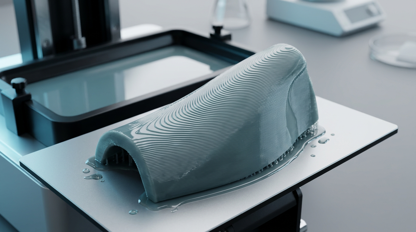
Visible contour-map-like lines on resin prints are frustrating because they often appear after the print has technically “succeeded.” The part does not fail, the supports hold, the shape is recognizable, but the surface shows repeated bands, waves, ridges, or curved lines that look like elevation lines on a map.
In resin 3D printing, this issue can come from both normal process geometry and abnormal workflow variation. Vat photopolymerization forms parts by curing liquid photopolymer resin with light in repeated layers, so the final surface is influenced by layer height, pixel resolution, resin behavior, part orientation, support stability, peel forces, and post-processing. NIST describes vat photopolymerization as a process where liquid photopolymer resin is cured with ultraviolet light over repeated stages to form solid structures. ASTM/ISO additive manufacturing terminology also defines additive manufacturing around the principle of building geometry by successive material addition.
For Yidimu’s professional customers, this matters in different ways. A factory may need smooth prototype surfaces for appearance review. A dental lab may need clean dental model surfaces for fit checking and communication. A model-making company may need reduced sanding time. A research team may need consistent test samples. A production team may need a stable process before moving from sample printing to batch workflow.
Yidimu provides industrial resin 3D printers, dental 3D printers, flexible resin 3D printers, 3D printing resins, UV curing equipment and workflow support for professional users. When contour map lines appear, the right solution depends on the full printing process, not only one slicer setting.
Why Resin Prints Can Show Contour Map Lines
Contour map lines usually describe one of four surface problems:
- Layer stair-stepping
Fine, evenly spaced lines caused by the layer-by-layer nature of printing. - Orientation-related contour bands
Curved lines that follow shallow surface angles, especially on domes, faces, dental arches, shells, product housings or smooth ergonomic shapes. - Mechanical or peel-force artifacts
Stronger bands caused by slight movement during lifting, suction release, weak support structure, loose build platform or Z-axis instability. - Post-processing-enhanced lines
Lines that become more visible after washing, drying, UV curing, sanding, priming or painting.
The first type is partly normal. The second can often be reduced by changing orientation and layer height. The third needs troubleshooting. The fourth requires better cleaning, curing and finishing control.
Research on additive manufacturing surface quality commonly describes the stair-stepping effect as a result of layered construction, and notes that build orientation and layer thickness can significantly affect surface quality. This principle applies broadly across additive manufacturing. In resin printing, the visual result may be finer than many extrusion processes, but shallow curves can still show layer transitions when the orientation and layer height are not suitable.
Practical Table: Causes and Fixes for Contour Map Lines
| Symptom on Resin Print | Likely Cause | What to Check | Practical Fix |
|---|---|---|---|
| Fine, regular lines across curved surfaces | Normal layer stair-stepping | Layer height, surface angle, model orientation | Reduce layer height if needed, rotate the model, place critical surface away from shallow build angles |
| Curved topographic lines on domes or smooth shells | Orientation mismatch | Slicer preview by layer, surface angle | Reorient the part so visible surfaces do not sit nearly parallel to the build plane |
| Thick bands at certain heights | Peel force, suction or support movement | Large cross-section area, hollow cavities, drainage holes, supports | Reduce suction area, add drainage holes, strengthen supports, lower lift speed |
| Wavy lines on support-facing side | Support deformation or resin film peel stress | Support density, contact points, bracing | Add lateral support, increase bracing, avoid large unsupported flat areas |
| Repeated horizontal bands on many prints | Z-axis or build platform issue | Z screw, rails, platform lock, vibration | Inspect mechanical tightness, clean and lubricate as recommended, confirm platform stability |
| Lines appear after curing or painting | Post-processing highlights surface texture | Washing time, drying, curing time, primer thickness | Improve cleaning, allow complete drying, use controlled UV curing, adjust finishing process |
| Lines only with one resin | Resin viscosity, exposure or temperature mismatch | Resin age, mixing, temperature, exposure test | Mix resin, stabilize temperature, recalibrate exposure for that resin |
| Lines plus dimensional distortion | Under-supporting or over-peel stress | Orientation, supports, lift/retract settings | Increase support strategy, reduce lift speed, add rest time, reduce cross-section per layer |
H2: When a 3d resin print has contour map lines, Start with Orientation
Print orientation is usually the first thing to review. Many users immediately change exposure time, but contour map lines often come from the relationship between layer height and surface angle.
A shallow curved surface printed almost parallel to the build plate can show visible bands because each layer creates a small step. The smaller the surface angle relative to the layer plane, the more obvious the contour pattern can become. This is why rounded model surfaces, dental arches, sculpted figures, product shells and ergonomic prototypes may show contour lines even when flat vertical walls look acceptable.
For industrial appearance prototypes, the best orientation is not always the fastest orientation. It is the orientation that protects the most important surfaces. For example, if a product development team prints a handheld device shell, the outer visible surface should be oriented to reduce stair-stepping and support marks, while less visible internal surfaces can accept more texture.
For dental model workflows, orientation also affects model base quality, arch surface smoothness, support placement and batch efficiency. Yidimu’s guide to dental 3D printer selection explains that dental results depend on the complete workflow, including printer stability, resin, file preparation, exposure settings and post-processing.
Orientation Checks
Before changing hardware or resin, inspect the sliced file:
- Does the line pattern follow the model’s curved geometry?
- Are the lines most visible on shallow slopes?
- Does the issue appear on only one surface direction?
- Are critical cosmetic surfaces facing the support side?
- Is the part creating a large cross-section during multiple layers?
- Is there a suction cup shape during printing?
If the contour lines follow the shape of the model very cleanly, the problem is likely geometric stair-stepping. If the bands are irregular, thick, shifted or appear at certain heights, mechanical movement or peel force may be involved.
H2: Layer Height and Surface Resolution
Layer height controls the vertical step between cured layers. A smaller layer height can reduce visible stepping, but it does not automatically solve every contour line problem.
For professional users, reducing layer height has trade-offs:
- Longer print time
- More layers to expose and peel
- Greater chance for accumulated process variation
- More demand on support stability
- Higher production cost per part
- More operator time before final inspection
A factory printing appearance prototypes may accept longer print time for smoother surfaces. A dental lab printing many models per day may prefer a balanced layer height that supports repeatability and throughput. A research center may choose layer height based on measurement requirements.
The key is to define which surface matters. Not every surface needs the same finish. For fixtures, jigs, internal test samples or non-cosmetic validation parts, slight layer texture may be acceptable. For dental models, customer presentation models, jewelry prototypes, shoe samples or display models, visible contour lines may require finer settings and better orientation.
H2: Suction Force and Peel Movement
In bottom-up resin printing, each cured layer separates from the release film or vat interface during lift movement. If the part has a large cross-section, hollow cavity, cup-shaped geometry or weak support structure, peel force can cause tiny movement. That movement may appear as bands or contour lines.
This is especially common when:
- The print has large flat areas
- The model is solid and heavy
- The part is hollow without enough drainage
- Supports are too thin or too vertical
- The build plate or Z-axis has slight looseness
- Lift speed is too aggressive for the resin and geometry
- Rest time is too short before exposure
- The resin is viscous or cold
- Flexible resin is used without support adjustment
For large industrial prototypes, suction management is critical. A smooth-looking CAD model may create difficult peel conditions if it has wide layers, closed cavities or flat surfaces. In that case, contour map lines are not only a cosmetic problem; they can indicate that the part is moving slightly during printing.
When printing flexible resin, the issue can be more sensitive because the material behavior may allow more deformation during peel movement. Professional users evaluating elastic samples should review flexible resin 3D printer workflows and test the actual part geometry rather than relying only on generic sample prints.
H2: Support Design Can Create or Prevent Contour Lines
Weak supports are one of the most common causes of strong contour lines. A print can remain attached to the build platform while still moving slightly during peel and retract cycles. This micro-movement may create horizontal bands, curved waves or uneven surfaces.
Professional support design should consider:
- Part weight
- Cross-section area per layer
- Direction of peel force
- Critical surface protection
- Lateral bracing
- Drainage for hollow parts
- Support contact size
- Support removal requirements
- Resin stiffness
- Print height and leverage
A common mistake is using supports that only hold the part vertically. Resin prints also need resistance against side-to-side movement. Tall parts, broad shells and flexible structures may need stronger lateral bracing.
For dental labs, support strategy should be matched to the dental application. Dental models, surgical guide workflows, temporary applications and appliance-related models may have different surface and post-processing requirements. Customers should confirm resin indication, post-curing process and local regulatory requirements before clinical or intraoral use.
H2: Exposure Settings and Resin Behavior
Exposure settings influence how well each layer cures and bonds to the previous layer. Underexposure may create weak layers, surface softness or support instability. Overexposure may reduce detail, increase dimensional deviation or make support marks more difficult to manage. Either condition can make surface lines more visible.
However, exposure should not be adjusted blindly. If a 3d resin print has contour map lines, first determine whether the lines are true layer geometry, peel-force movement or exposure instability.
Check these factors:
- Resin type and recommended wavelength
- Resin age and storage condition
- Whether resin was mixed before printing
- Ambient and resin temperature
- Layer height
- Normal exposure time
- Bottom exposure time
- Transition layers
- Lift speed and retract speed
- Rest time before exposure
- Light uniformity and screen condition
- Vat film condition
Professional workflows should document parameter changes. Changing exposure, support density, orientation and lift speed all at once may make it harder to find the real cause. For production teams, parameter control is part of quality control.
Yidimu’s 3D printing resin selection support can help customers evaluate resin choice according to surface finish expectations, model size, flexibility, dental workflow, industrial prototype requirements and curing process.
H2: Mechanical Stability and Z-Axis Issues
If contour lines appear as repeated horizontal bands on different models, different orientations and different resins, the printer hardware should be checked.
Possible mechanical causes include:
- Loose build platform
- Build plate locking mechanism not fully tightened
- Z-axis screw contamination
- Rail friction
- Worn or dirty motion components
- Vat or film tension issue
- External vibration
- Unstable table or floor
- Printer not level
- Screen or light source issue
- Resin vat not seated correctly
A professional resin printer should be evaluated over repeated prints, not only one successful sample. Repeatability is especially important for dental labs, factories and model-making teams that depend on predictable output. Yidimu’s technical team notes that actual printing results may vary depending on printer model, resin type, model structure, slicing settings, exposure parameters, support design, cleaning process, UV curing and working environment.
H2: Post-Processing Can Make Lines Look Worse
Sometimes the print already has fine layer texture, but washing, drying, curing or painting makes it more visible.
Common post-processing causes include:
- Over-washing delicate surfaces
- Using contaminated wash liquid
- Not drying the part fully before curing
- Uneven UV curing
- Over-curing thin parts
- Aggressive support removal
- Sanding in the wrong direction
- Primer that settles into layer grooves
- Glossy paint that highlights surface bands
For professional users, post-processing should be standardized. Washing time, solvent condition, drying method, UV curing duration, curing box wavelength and part orientation during curing can all affect final surface quality. Many resin workflows require controlled cleaning and UV curing; the exact process depends on the resin, printer, part size and application. Yidimu provides UV curing boxes as part of complete resin printing workflows.
Workflow or Checklist: How to Troubleshoot Contour Map Lines
Use this checklist before changing too many settings.
Step 1: Identify the Pattern
Ask:
- Are the lines evenly spaced?
- Do they follow the model’s curved surface?
- Are they only on one side?
- Are they horizontal bands across the full part?
- Are they stronger near large cross-sections?
- Do they appear on every print or only one model?
If the lines follow the geometry, suspect stair-stepping and orientation. If they appear as shifted bands, suspect movement, suction or hardware stability.
Step 2: Review the Sliced Layers
Open the sliced file and inspect:
- Layer preview
- Surface angle
- Cross-section size per layer
- Hollow cavities
- Cup-like shapes
- Drainage holes
- Support contact points
- Support bracing
- Critical visible surfaces
If the slicer preview already looks like contour lines on shallow curves, orientation or layer height is likely involved.
Step 3: Reorient the Model
Try a controlled test:
- Rotate the part to reduce shallow visible surfaces
- Move support marks to less critical areas
- Avoid large flat surfaces parallel to the build plate
- Reduce sudden cross-section changes
- Avoid cup-shaped suction where possible
Do not judge by angle alone. Judge by surface importance, support strategy and cross-section behavior.
Step 4: Strengthen Supports
Improve support stability:
- Add supports to resist lateral movement
- Increase support density in heavy zones
- Add bracing between tall supports
- Use stronger supports at the first contact points
- Avoid long unsupported spans
- Protect the most visible surface from support marks
For production parts, create a documented support template after testing.
Step 5: Reduce Suction and Peel Stress
Check:
- Hollow model drainage
- Vent holes
- Wall thickness
- Lift distance
- Lift speed
- Rest time
- Cross-section area
Large parts may need slower lift settings and better drainage. Flexible resin may need additional support and conservative peel settings depending on the part.
Step 6: Calibrate Exposure for the Resin
Run a controlled exposure check for the actual resin and layer height. Avoid assuming that one resin’s setting works for another.
Confirm:
- Normal exposure
- Bottom exposure
- Transition layers
- Resin temperature
- Mixing before printing
- Resin cleanliness
- Vat film condition
Step 7: Inspect Printer Mechanics
If the same lines appear across different files, inspect:
- Build plate tightness
- Z-axis rails
- Lead screw
- Printer level
- Vat seating
- Table vibration
- Screen and light uniformity
- Maintenance schedule
Document maintenance, especially in labs or factories with multiple operators.
Step 8: Standardize Post-Processing
Control:
- Washing method
- Washing liquid condition
- Drying time
- UV curing time
- Part orientation during curing
- Support removal timing
- Surface finishing method
For dental applications, customers should confirm resin indication, post-curing process and local regulatory requirements before clinical or intraoral use.
H2: Professional Application Notes
Industrial Prototyping
For industrial prototypes, contour map lines may affect visual approval, customer presentation and fit testing. If the part is used only for internal structural review, mild layer lines may be acceptable. If it is used for appearance validation, surface finish should be planned before printing.
Yidimu can help factories evaluate industrial resin 3D printing workflows based on model size, surface detail, resin requirement and post-processing expectations.
Dental Labs and Clinics
Dental models often have curved arches, vertical walls, bases and fine anatomical features. Contour lines may appear on curved surfaces when orientation and layer height are not optimized.
Dental applications should be treated carefully. Printed dental parts may require specific resin indications, washing, UV curing, documentation and local regulatory review. Customers should confirm resin indication, post-curing process and local regulatory requirements before clinical or intraoral use.
Model-Making Companies
For model-making, contour lines may increase finishing labor. The best solution is often a combination of orientation, smaller layer height, support strategy and controlled sanding/priming.
Flexible Resin Samples
Flexible samples can deform during peel movement if the support strategy is too light. For soft parts, test actual geometry and expected handling conditions. Do not judge material suitability only from a small generic benchmark sample.
Research and Engineering Teams
Research users should record all process settings. Contour map lines can influence measurement, optical inspection and surface-dependent testing. Keep orientation, layer height, exposure, resin batch, curing process and ambient conditions documented.
Common Mistakes to Avoid
Mistake 1: Only Reducing Layer Height
Lower layer height may improve stair-stepping, but it does not fix weak supports, suction, Z-axis movement or poor post-processing. It also increases print time.
Mistake 2: Ignoring Orientation
Many contour line problems begin before printing. If the model is oriented poorly, even a stable printer may produce visible surface bands on shallow curves.
Mistake 3: Using Auto Supports Without Review
Auto supports can be useful, but professional parts need manual review. Critical surfaces, heavy zones, lateral stability and suction areas should be checked.
Mistake 4: Printing Large Solid Parts Without Suction Planning
Large solid or cup-like parts can create strong peel forces. Hollowing, drainage and orientation should be reviewed carefully.
Mistake 5: Changing Too Many Settings at Once
If you change orientation, exposure, lift speed, support style and resin at the same time, you may not learn which factor caused the improvement or failure.
Mistake 6: Treating All Resins the Same
Model resin, dental resin, engineering resin and flexible resin can behave differently. Exposure, support and post-processing may need adjustment.
Mistake 7: Skipping UV Curing Control
Uncontrolled curing can affect surface appearance, strength and stability. A professional workflow should use a repeatable curing process.
Mistake 8: Blaming the Printer Before Checking the File
Sometimes the issue is already visible in the sliced geometry. Always inspect the sliced file before assuming hardware failure.
H2: How to Decide Whether the Lines Are Acceptable
Not every visible line requires the same response. Use the final application to decide.
| Application | Surface Line Tolerance | Recommended Action |
|---|---|---|
| Internal engineering fit check | Medium | Accept mild lines if dimensions are suitable |
| Appearance prototype | Low | Optimize orientation, layer height and finishing |
| Dental study model | Low to medium | Confirm workflow consistency and model purpose |
| Surgical guide or intraoral-related workflow | Very low, application-dependent | Confirm resin indication, curing process and local requirements |
| Flexible sample | Medium, depends on testing purpose | Balance surface finish with flexibility and support removal |
| Display model | Low | Use smoother settings and finishing workflow |
| Research sample | Depends on test method | Document all settings and inspect surface consistency |
H2: When to Ask for Technical Support
Contact technical support when:
- Lines appear across multiple models and resins
- The same band appears at the same height
- Prints show both lines and dimensional shift
- Supports are stable but surfaces still move
- Large parts fail during peel movement
- Dental model accuracy is inconsistent
- Flexible resin parts deform during printing
- Post-curing changes surface appearance unexpectedly
- Your team needs a repeatable production workflow
When contacting Yidimu, provide:
- Model size
- Resin type
- Layer height
- Print orientation screenshots
- Support screenshots
- Exposure settings
- Lift and retract settings
- Photos of the lines
- Application requirement
- Expected workflow
- Post-processing method
For new projects, customers can request sample printing support before choosing a complete printer, resin and curing workflow.
Conclusion
If a 3d resin print has contour map lines, do not treat it as a single-setting problem. Fine lines may come from normal layer stair-stepping, but strong contour bands usually point to orientation, suction force, weak supports, exposure mismatch, mechanical instability, resin behavior or post-processing inconsistency.
For professional users, the best solution is a controlled workflow: inspect the sliced file, improve orientation, strengthen supports, reduce suction, calibrate exposure, check mechanical stability and standardize washing and UV curing. The right setup depends on model size, resin requirement, surface finish expectation, dental or industrial application and production volume.
Yidimu helps factories, dental labs, clinics, model-making companies and R&D teams select suitable resin printers, materials and post-processing workflows. To discuss your project, contact Yidimu with your model size, resin requirement, application, expected surface quality and daily workflow so the team can help review a practical equipment and process plan.
FAQ
Why does my resin print have contour map lines?
A resin print may have contour map lines because of layer stair-stepping, shallow surface orientation, suction force, support movement, exposure inconsistency, Z-axis instability, resin temperature variation or post-processing that highlights surface bands.
Are contour lines normal on resin 3D prints?
Fine layer texture can be normal because resin printing builds parts layer by layer. However, strong, thick, wavy or repeated bands are usually a sign that orientation, supports, suction, exposure or mechanical stability should be checked.
Will lowering layer height remove contour map lines?
Lowering layer height may reduce stair-stepping, but it may not remove lines caused by suction, weak supports, Z-axis movement or incorrect exposure. It also increases print time, so professional users should balance surface quality and throughput.
What print orientation reduces contour lines?
A better orientation reduces shallow visible slopes, avoids large flat cross-sections, moves support marks away from critical surfaces and limits suction. The best angle depends on the model geometry and the surface that matters most.
Can supports cause contour map lines?
Yes. Weak supports can allow slight movement during lift and peel cycles. This movement may create bands, waves or uneven surfaces even if the print does not fully fail.
Can resin temperature cause surface lines?
Resin temperature may affect viscosity, flow and curing behavior depending on the material. Unstable temperature can contribute to inconsistent results, especially in professional workflows that require repeatability.
Do contour lines mean my Z-axis is bad?
Not always. Many contour lines are caused by orientation or support issues. However, if the same bands appear at similar heights across different models and resins, Z-axis stability, build plate tightness and printer mechanics should be inspected.
Why are lines worse on curved or dome-shaped resin prints?
Curved surfaces can show stair-stepping more clearly, especially when the surface angle is shallow relative to the build layers. Reorientation and suitable layer height can often reduce the effect.
Can UV curing make contour lines more visible?
Yes. Uneven or excessive post-curing may make surface texture more noticeable. Washing, drying, curing time and part orientation during curing should be controlled.
Are contour lines a problem for dental prints?
They can be, depending on the application. For dental model workflows, surface consistency and fit may matter. Customers should confirm resin indication, post-curing process and local regulatory requirements before clinical or intraoral use.